


 6 / 84

6
Criteria for determining the cable track loading capacity
Besides requirements for loading capacity of cable track, its stiff-
ness is also of key importance. It is assessed by maximum value of
bending of loaded track.
Cable trays LINEAR were tested acc. to regulation ČSN EN 61 537
ed. 2. Samples of cable trays were loaded gradually (by steps) up
to loading SWL which is the maximum value of loading under which
the bending of trays meassured in half of distance between their
supporting points does not exceed 1/100 of distance between
supporting points. Simultaneously diagonal bending of any width
must not exceed 1/20 of width of the sample. Tested tray samples
were then gradually loaded up to 1.7 times SWL without cracking
of trays. If both of these conditions are fulfilled, the tested tray re-
cieves certification.
We set higher requrements for system LINEAR (see table below)
and permissible values are set to 1/150 of bending in half of dis-
tance between supporting points. Simultaneously diagonal bend-
ing of any width must not exceed 1/20 of width of the tray.
To reach the declared values, it is necessary to maintain way of in-
stallation. Especially type and usage of supporting elements and
installation of joints.
Stiffer trays mean among others better conditions for functioning
of cabling, especially under extreme conditions.
max. bending of LINEAR trays
h
M2
= 1/150
×
L
max. bending according to ČSN EN 61 537
L
h
max
= 1/100
×
L
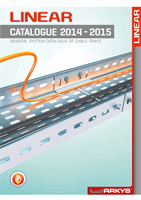
width
[mm]
thickness
[mm]
supporting points distance
1000 mm 1250 mm 1500 mm 1750 mm 2000 mm
100, 120, 160 0,8
89 kg/m 78 kg/m 68 kg/m 60 kg/m 53 kg/m
200, 260 1,0
107 kg/m 103 kg/m 97 kg/m 92 kg/m 84 kg/m
300, 400, 500 1,2
129 kg/m 118 kg/m 111 kg/m 102 kg/m 96 kg/m
30
40
50
60
70
80
90
100
110
120
130
1 000 1 250
1 500
1 750 2 000
[kg/m]
[mm]
200, 260 mm
100, 120, 160 mm
300, 400, 500 mm
Maximum permissible loading values of trays H=50 mm
table and charts apply for LINEAR 1 and LINEAR 2 and coupling placing regardless of position.
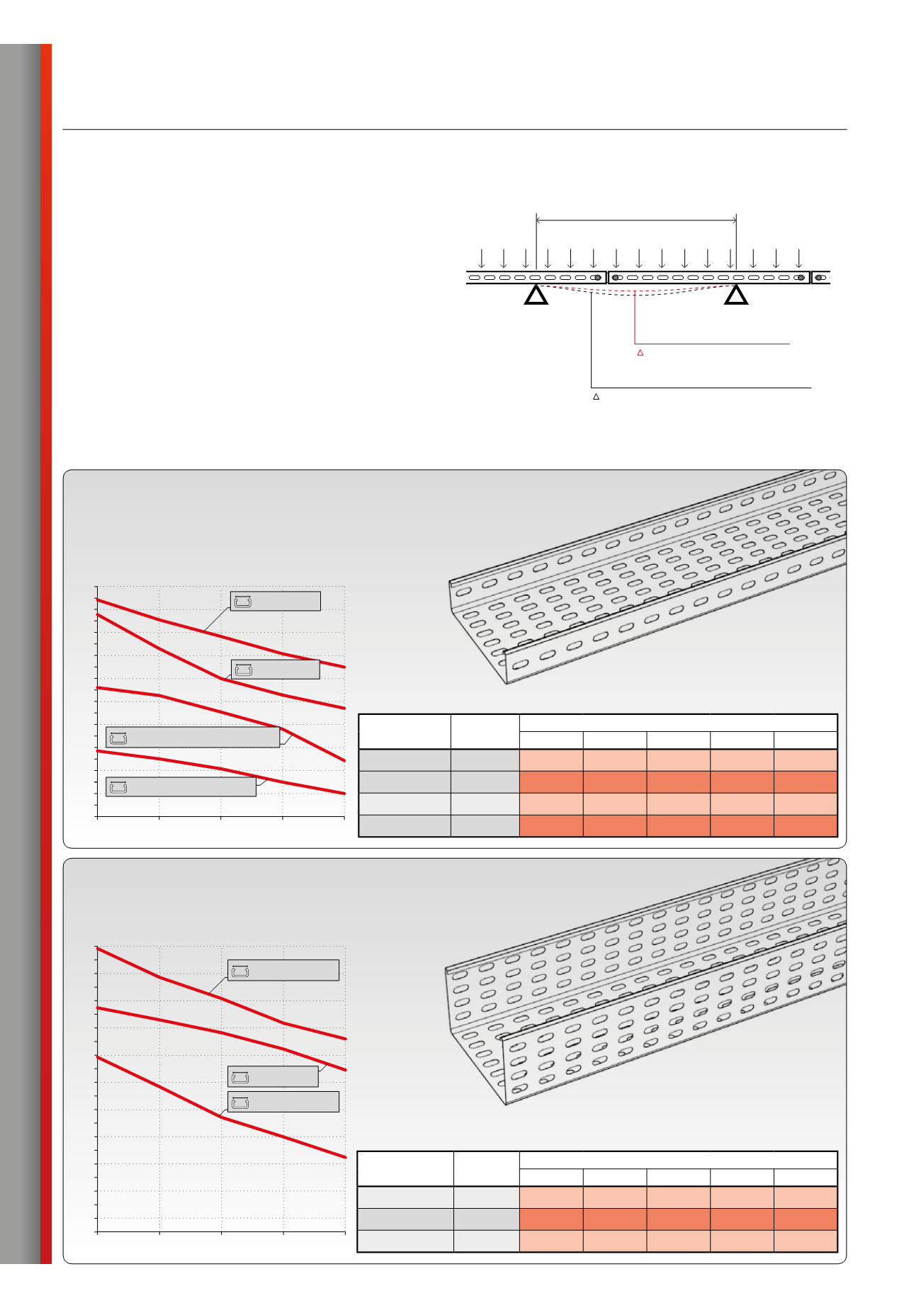
width
[mm]
thickness
[mm]
supporting points distance
1000 mm 1250 mm 1500 mm 1750 mm 2000 mm
50 - 120 0,6
37 kg/m 34 kg/m 31 kg/m 26 kg/m 20 kg/m
50 - 200 0,8
66 kg/m 63 kg/m 56 kg/m 47 kg/m 36 kg/m
260, 300 1,0
97 kg/m 83 kg/m 70 kg/m 63 kg/m 57 kg/m
400, 500 1,2
104 kg/m 96 kg/m 88 kg/m 81 kg/m 75 kg/m
30
20
10
40
50
60
70
80
90
100
110
1 000 1 250
1 500
1 750 2 000
[kg/m]
[mm]
400, 500 mm
50, 100, 120, 160, 200, 260 mm
260, 300 mm
50, 100, 120 mm/t=0,6mm
Maximum permissible loading values of trays H=50 mm
table and charts apply for LINEAR 1 and LINEAR 2 and coupling placing regardless of position.
weight limits in table and chart apply also for trays H=60mm