Impact of joint location upon the loading capacity and stiffness of the cable route
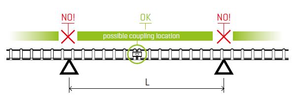
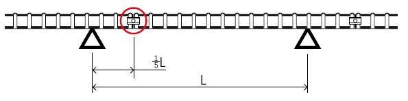
In terms of functionality and rigidity of a cable route, the ideal connecting point of particular mesh trays ought to be located at 1/5 of the support points span. In such case the loading capacity and the rigidity of the cable route achieve the best values. On the contrary, locating the connecting point directly above the support point severely decreases the mesh tray loading capacity. Consequently, the mesh tray joints must not be placed directly above the mesh tray support point in any type of installation.
In the light of field experience in assembling cable routes it is obvious that it is not always possible to achieve the ideal position of the joints. Hence we test our cable routes for installations with arbitrary location of the joint and proven load parameters of a cable route installed in such way (meaning when SZM 1 connectors are placed anywhere else except for directly above the support points of the route) are available. In order to set the maximum load capacity of a cable route, there are two types of installation - see the following schemes.
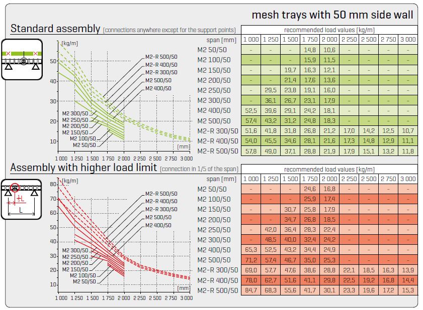
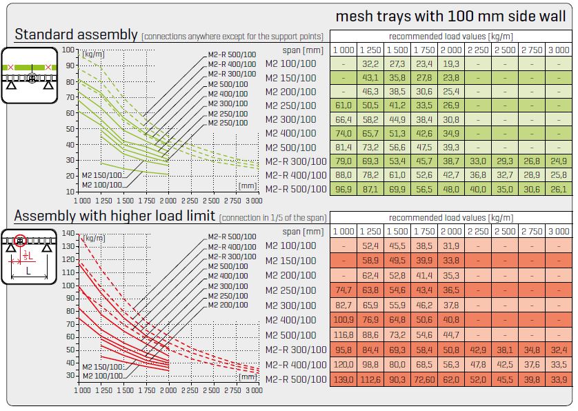
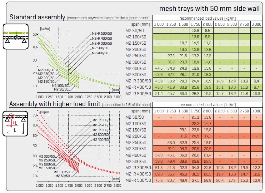
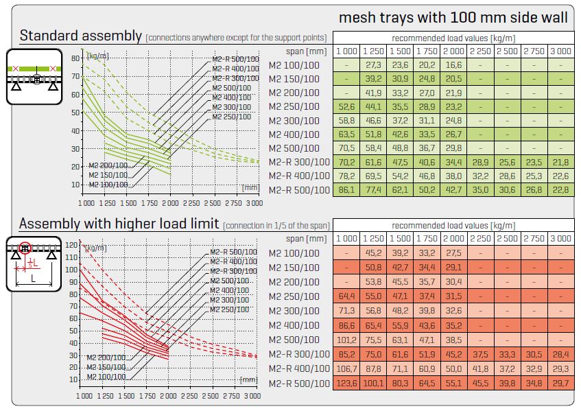
Standard assembly (connection anywhere except for the support points)
This type of installation is considered to be standard as almost no requirements on joint location arise except for being placed directly above the support point. Hence there is no need to shorten the mesh trays and the installation waste is minimized. This type of installation is suitable for standard cable routes. With usual span of support points, it provides higher maximum loading capacities than the utilizable loading capacity - see the following chapters and loading capacity charts below.
Higher load capacity assembly (connection located at 1/5 of the support points span)
This type of installation is rather demanding, as the condition of placing the joints precisely leads to shortening of each mesh tray, thus to larger waste quantity and to lower economical effectivity. Consequently, this type of installation is suitable especially for very loaded cable routes or for technically challenging sections where a larger span of supports is needed. However, it provides considerably higher loading capacity, up to twice the value of the standard installation.
Mesh tray load control
The overall load of the route is the sum of the mass of all cables carried by the route, including all accessories suspended on the cable mesh trays. In other words, dividers and covers of cable routes, junction boxes, suspended lamps etc. should be comprised in this total. However, the cabling usually prevails. To calculate the load with cables, the indicative weight of individual cable types and sizes can be used, as stated in the table of characteristics of common cables (p. 8). The calculated load capacity of a mesh tray must be compared to the maximum admissible figures according to the certificate valid for particular mesh tray dimension. When examining the load capacity of the cable route, it is also necessary to consider the type of installation, especially the position of connecting points. If the DZM 3/100, DZM 3/150, DZM 4 and DZM 6 holders are used to carry the mesh tray, it should be considered that the assembly provides no supports from the bottom, but the suspension of the mesh tray using the upper edge wire. In such case the safety coefficient of 0.7 should be used for all values indicated in the tables and graphics on p. 11.
Criteria for determining the cable route loading capacity
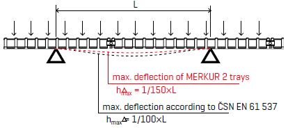
In addition to the load capacity also the rigidity of the cable route is decisive for its design. It is assessed according to the maximum deflection of a loaded route. The MERKUR 2 mesh trays have been tested for compliance with the ČSN EN 61 537 ed. 2 standard. Samples of mesh tray routes were loaded gradually (in steps) up to the SWL load, which is the maximum load value for which the mesh tray deflection measured at the middle between the support points does not exceed 1/100 of the span. At the same time, the transverse deflection at each span must not exceed 1/20 of the sample width. The tested mesh tray samples were further loaded gradually to 1.7 times the SWL load whilst, according to the standard, the mesh tray construction shall not get distorted. If both these conditions are met, the tested cable mesh tray will be issued the certificate.
The MERKUR 2 cable trays are designed with higher reserve and even under the maximum allowed load (see tables of recommended and maximum admissible loading capacity on following pages) their deflection does not exceed the value of 1/150 of the span between the support points. This means that, for example, if the span is 2,000 mm, the absolute deflection value does not exceed 13 mm (whilst, according to the standard requirements, the allowed deflection is permitted to reach 20 mm!). Stiff mesh trays offer, among others, better conditions for the cabling function, namely under extreme conditions. This became evident e.g. during the fire resistance testing where M2 trays achieved excellent resistance values (see more on this topic in chapter Routes installation requiring functional integrity in fire on pages 56-78).
Considering the situation on the market, where the loading capacity figures presented by the majority of manufacturers and distributors are in reality the limit values of their mesh trays loading capacity, we present our standard recommended loading capacity with higher safety margin together with maximum admissible loading capacity of M2 mesh trays to allow comparison of both values. See more details in tables on following pages of this catalogue.
Real loading capacity of mesh trays
The previous paragraphs were dealing with weight and loading capacity of cable constructions in general, with regard to general load of the cable route with continuous weight distribution. However, the installed cabling situation is specific - the electric cables are practically the only effective load of the cable route. The exception is represented only by special types of installation like self-supporting cable routes with directly installed lighting elements etc. Usually almost 100% of the mesh trays load consists solely of the installed cabling. If we take into consideration the available crosssection of the mesh trays and the usual specific weight, we obtain the following results:
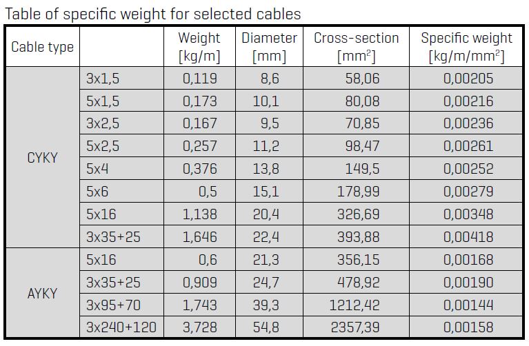 The previous table shows that the specific weight of cables does not exceed the value of 0,0028 kg/m/mm2. Only cables of large diameter and of low flexibility (hence of higher degree of self-support) reach higher values of specific weight. This is also reached by larger diamener with lower coefficient of filling the available cross-section of the mesh tray. This information has actual influence on construction load, as the previous chapters tell us that we only can place an appropriate number of cables into a particular rated mesh tray crosssection, the weight of cables will then load down the cable route. When we apply this knowledge on effective mesh tray cross-section, we obtain the following table showing the maximum possible load of a mesh tray, loaded with cabling.
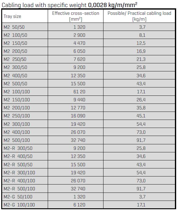 The previous table proves that the real values of mesh tray load with cables are relatively low and that high values are reached only with the largest mesh trays dimensions. Typical dimensions of mesh trays up to 300mm wide reach the load values of max. 25 kg/m (with the 50 mm side wall), or 55 kg/m (with the 100 mm side wall). The only exception is represented by the largest mesh tray dimensions, where it is more convenient to use the reinforced M2-R mesh trays, which permits to keep larger span between the anchorage points on the route, despite high specific load of the route. All this information brings us to conclustion that in standard realizations of cable routes it is not possible to load the mesh trays by the cabling in such way to achieve the limit values of their load capacity.
Recommended load values | values according to standard methodology of M2 mesh trays tests
Maximum allowed load values | values according to methodology of ČSN EN 61 537 norm