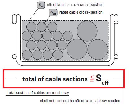
There are two crucial parameters to determine the right mesh tray size. The total number of cables to be put in a mesh tray is represented as the total sum of the nominal sections of all cables to be placed in the tray (see below). The second parameter is represented by the effective mesh tray cross-section.
Utilisable mesh tray cross-section
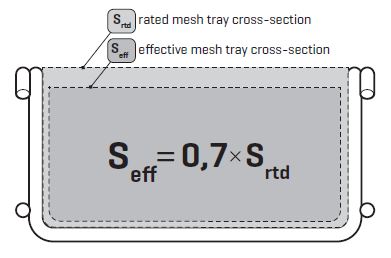
 The utilisable mesh tray section is a value defining the sum of the sections of all cables that can be carried by a given mesh tray, plus a certain safety reserve. The safety reserve is intended, e.g., to cope with the increased need for space at the points of route bending, with less efficient utilization of the existing room if quite a number of cables are carried in one single track, and it also accounts for possible further wishes to add some new cabling to the cable route, plus similar issues that can occur later on.
Every tray is defined by its effective cross-section value, which helps to calculate the cable route in accordance with the presumed number of cables of a particular diameter in each layer.
Necessary cross-section Stot
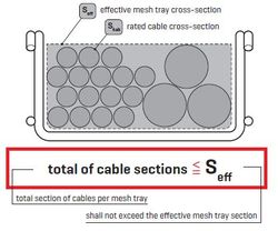 The section is defined as the total sum of the nominal sections of all cables to be placed in a cable route. Our indicative tables containing sections of the most frequently used cables are meant as an aid in determining the section of individual mesh trays. They are merely informative; for accurate data that you may need for your calculations, please consult the manufacturer of the cabling you intend to use. Compare the calculated value of the required tray section (Stot) with the values of the effective mesh tray sections (Seff) and find the appropriate one - its value is the same or higher than the required tray section (Stot).
At the same time, the purpose of the route and cooling system requirements should be taken into account and, accordingly, it is preferable to choose wider cable trays with some vacant space, i.e. lowe¨r filling rate. For better cooling it is also recommended to reduce the number of layers in which the cables are placed.